
Working Principle of the Curtis Controller on Electric Forklifts
Th10
Working Principle of the Curtis Controller on Electric Forklifts
⚡ 1. What Is a Curtis Controller?
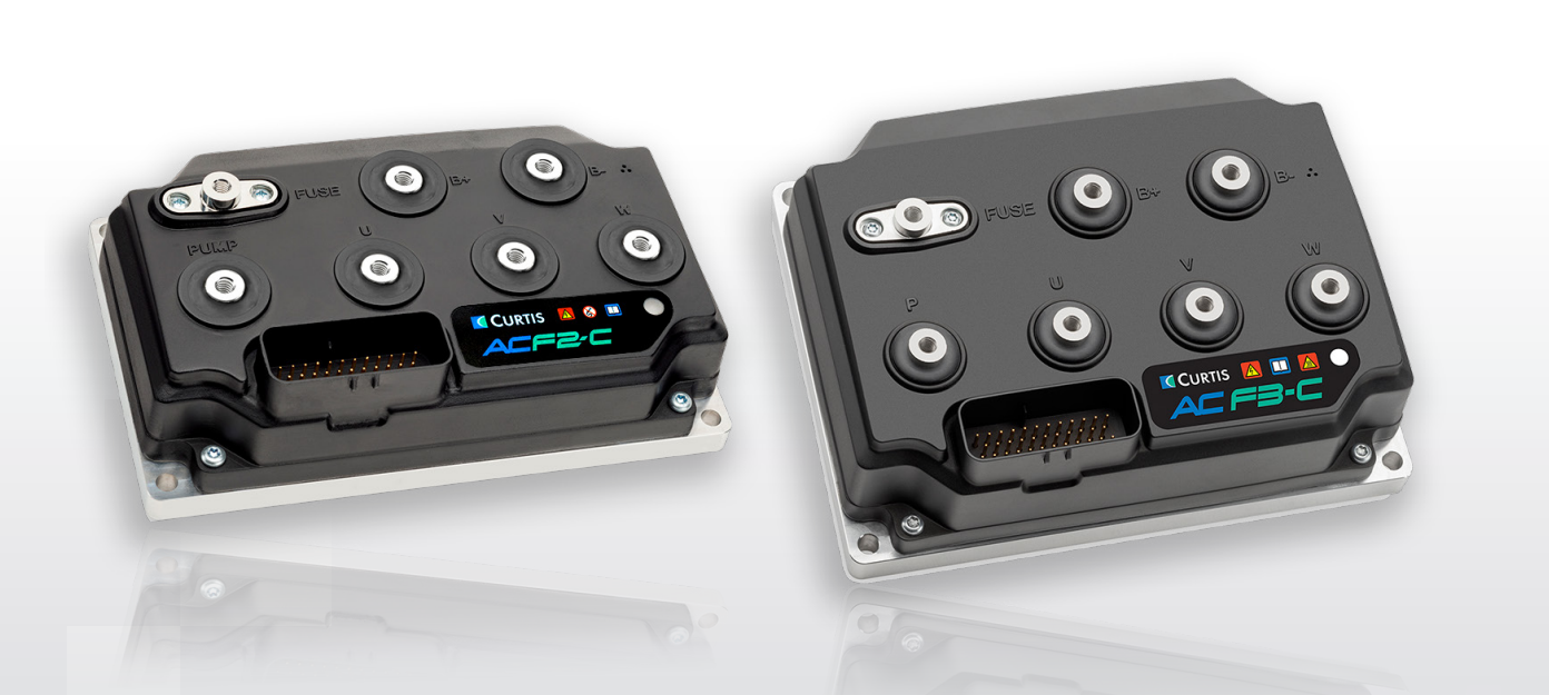
The Curtis Controller is the central control unit of an electric forklift, developed by Curtis Instruments (USA).
It functions as the “electronic brain” that manages drive motors, lift motors, braking, and overall vehicle safety.
Curtis controllers are widely used in brands like EP Equipment, Toyota, Linde, Yale, Hyster, thanks to their precision, durability, and smart control technology.
⚙️ 2. Main Components of the Curtis Controller
| Component | Function |
|---|---|
| CPU (Microprocessor) | Processes signals from throttle, brake, and sensors to control the motor. |
| Power Circuit (MOSFET / IGBT) | Generates PWM pulses to regulate motor voltage and current. |
| Current Sensor | Measures output current to protect the system from overcurrent. |
| Position Sensor / Encoder | Provides rotor speed and position feedback (especially for AC motors). |
| Regenerative Circuit | Converts braking energy into electrical energy to recharge the battery. |
| Protection Circuit | Monitors temperature, voltage, and motor errors for safe operation. |
🔄 3. Working Principle of the Curtis Controller
🔹 3.1. Startup Phase
When the power switch is turned on, the Curtis controller performs a self-check:
-
Battery voltage level
-
Brake status
-
Throttle position (must be zero)
If all conditions are met, the READY light turns on — the forklift is ready for use.
🔹 3.2. During Acceleration
-
The throttle signal (0–5V or Hall sensor) is sent to the CPU.
-
The CPU generates PWM (Pulse Width Modulation) signals to control the MOSFET/IGBT.
-
The controller smoothly increases motor voltage and current → smooth acceleration.
🔹 3.3. Direction Change
-
The Curtis reverses current polarity (DC motor) or phase order (AC motor).
-
The system limits speed during reversing to prevent mechanical shock.
🔹 3.4. Braking / Releasing Throttle
-
The controller narrows the PWM pulse width → motor decelerates.
-
The motor acts as a generator, converting kinetic energy back to electrical energy — this is regenerative braking, improving efficiency and extending battery life.
🔹 3.5. Fault or Overload Protection
The Curtis constantly monitors:
-
Output current
-
Power temperature
-
Sensor feedback
If abnormal conditions are detected:
-
Overcurrent → PWM cutoff
-
Overheat → reduce power or stop output
-
Sensor error → display fault code via LED or screen
🔁 4. Control Cycle Example (Curtis 1236 – AC Motor)
This loop repeats hundreds of times per second, ensuring precise and smooth motor control.
💡 5. Key Advantages of the Curtis Controller
-
Smooth and accurate motor control via high-frequency PWM
-
Regenerative braking saves 15–25% of energy
-
Self-diagnostic system with fault codes
-
Customizable via Curtis PC software or Handset:
-
Maximum speed
-
Acceleration / deceleration
-
Current limits
-
Braking strength
-
⚙️ 6. Connections Between Curtis and Other Components
| Component | Function |
|---|---|
| Throttle | Sends speed request signal |
| Forward/Reverse switch | Determines motor direction |
| Electromagnetic brake | Controlled by Curtis output |
| Motor | Receives PWM power from controller |
| Encoder / Hall Sensor | Provides feedback signals |
| Battery / Main contactor | Power source and safety cutoff |
🧠 7. Conclusion
The Curtis controller is truly the central brain of an electric forklift.
It ensures:
-
Smooth operation
-
Energy efficiency
-
Safe, reliable performance
When maintaining or replacing a Curtis controller, make sure the model and voltage match your motor system for best results.